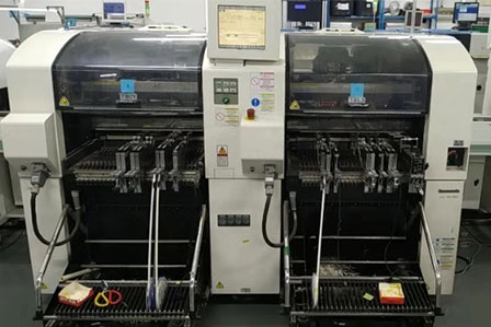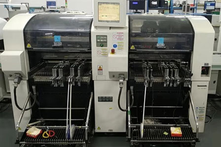

SMD vision system

Vision centering systems are commonly used in high-performance placement machines. The vision centering system uses digital image processing technology. When the nozzle on the chip head picks up the components, it is obtained by a camera fixed on the chip head a certain position on the fuselage during the process of moving to the chip position. Images, through the optical density distribution of the image detection elements, these optical densities are digitally passed through a CCD photocoupler array composed of many small precise photosensitive elements on the camera to output gray values of 0 to 255. The gray value is proportional to the optical density. The larger the gray value, the clearer the digitized image. The digitized information is stored, coded, amplified, sorted, analyzed, the results are fed back to the control unit, the processed results are output to the servo system to adjust the position deviation absorbed by the compensation components, finally the placement operation is completed [3].
So, after the machine takes pictures of the reference points components on the PCB, how to achieve automatic correction of the placement position achieve placement? In this process, the machine locates the placement target of the component by transforming between a series of coordinate systems. We explain how the system works through the placement process. First, the PCB is transferred to a fixed position by a transfer device fixed by a clamping mechanism. The placement head is moved above the PCB reference point, the camera on the head takes a picture of the reference point on the PCB. At this time, there are 4 coordinate systems: the substrate coordinate system (Xp, Yp), the camera coordinate system on the head.
(Xca1, Ycal), image coordinate system (Xi, Yi), machine coordinate system (Xm, Ym). After the reference point is photographed, the machine converts the substrate coordinate system into the machine coordinate system through association with the camera the image coordinate system, so that the target placement position is determined. Then the picker picks up the component moves to the fixed camera position, the fixed camera takes a picture of the component. At this time, there are also four coordinate systems: the head coordinate system is also the nozzle coordinate system (Xn, Yn), the fixed camera coordinate system (Xca2, Yca2), the image coordinate system (Xi, Yi), the machine coordinate system (Xm, Ym). ). After the components are photographed, the machine calculates the center position coordinates of the component features in the image coordinate system transforms them into the machine coordinate system through association with the camera image coordinate system. At this time, the component center coordinates suction are compared in the same coordinate system. Mouth center coordinates. The difference between the two coordinates is the required position deviation compensation value. Then according to the target placement position determined in the same coordinate system, the machine control unit servo system can control the machine for placement.
13962439646
Address: No.333 Youbi Road, Zhoushi Town, Kunshan City, Suzhou City
Email: srd@kunshansmt.cn
